
List View
The devices in a system can be viewed in two ways: List View (default) and Matrix View.
The List View contains two panels:
- Source devices (encoders) and multiview configurations are shown in the panel on the left.
- Destination devices (decoders) and walls are shown on the right.
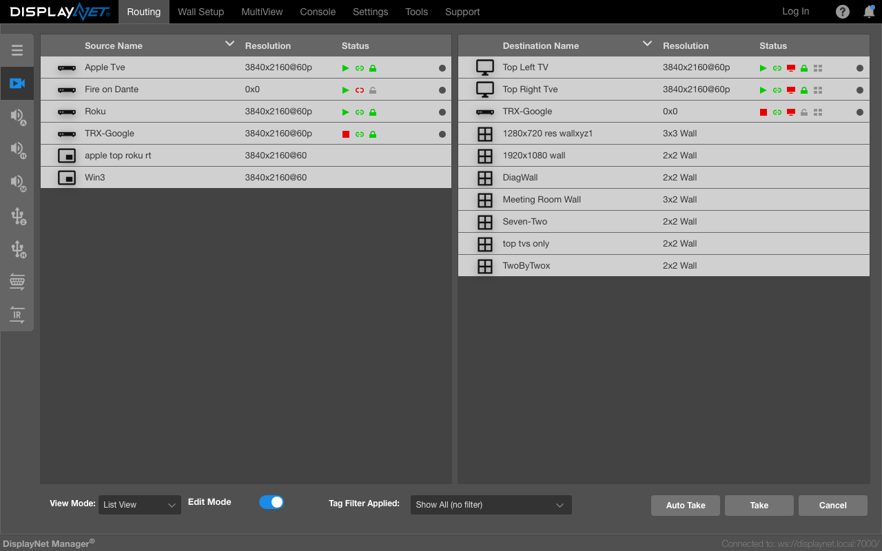
Sources and Destinations Panels
The Sources and Destinations Panels show the DisplayNet transmitter and receiver devices (except the Video Layer which will also display any saved multiview configurations and wall configurations). Transmitter devices are shown in the Sources Panel on the left; and receiver devices are shown in the Destinations Panel on the right. Each device is shown as a separate row. If there are more devices available than can be shown within each panel, then a vertical scroll bar will appear.
Device Rows
In the Sources and Destinations Panels, a "Device Row" represents each DisplayNet transmitter and receiver. Each row contains the Device Icon and the Host Name, as well as other information, such as the current resolution, device status, text and/or icons.
Right-clicking on a Source or Destination device will bring up a menu with several available options depending on the routing layer and the device status. This is called the Device Row Submenu.
Double-clicking on a Device Row will open the Device Settings for that device.
Device Icon
Each device can be assigned a unique Device Icon. By default, the Set-Top Box icon is assigned to Source devices and the Monitor Dark icon is assigned to Destination devices. The icon assigned to a device can be changed using the Device Settings.

Host Name
Each device includes a Host Name that can be defined in its Device Settings. This is a short name (up to 19 characters), which is stored within the DisplayNet device. This name will be provided to any control device connected to the network. By default, the Host Name for each device is set to the MAC Address of that device. A device can be renamed using the Device Settings.

Resolution
In the Video Routing Layer, the Device Rows include a resolution field. Usually, the last known resolution of the video signal is shown here. For more detailed information about the video signal, such as bit depth and color space open the Video Tab in the Device Settings for that device.

The resolution is shown in the following format:

i.e., 3840 pixels wide and a height of 2160 pixels with 24 frames per second (fps)
The following resolution status readout values are possible:
| Status | Description |
|---|---|
| Resolution | Current resolution being streamed. |
| 0 x 0 | Device is active and not receiving a video stream. |
| Disconnected | Device has been removed from the network or has lost power. |
| #x# Wall | Wall configurations will show their grid size (2x2, 3x3, etc.) in the resolution field. |
A receiver will display the last known resolution in its Device Row until a new stream is received or another change takes place.
If a device is disconnected from the network, then its Device Row will appear dark gray and in the resolution field, the word "Disconnected" will appear.
If a device is being used in an active Wall Configuration, the Device Row will show the output resolution of only the segment of video being shown on that display. This will often be a non-standard resolution.
Status
This section contains icons or text that offer a quick view of the status of each device. Different icons are displayed based on which routing layer is currently selected.

Transmitter Device Status
| Video Source Status | Icon / Text | Layer | Description |
|---|---|---|---|
| Video Source Status |   | Video Video | The TX is disconnected from the source or is not receiving a stable signal. The TX is connected to the source and is receiving a stable signal. |
| Video Stream Status |   | Video Video | The video stream from the TX is stopped. The video stream from teh TX is started. |
| HDCP |   | Video Video | The source signal is not HDCP encrypted. The source signal is HDCP encrypted. |
| Audio Stream | Stopped Streaming | Analog, Downmixed Analog, Downmixed | The audio stream from the TX is stopped. The audio stream from the TX is started. |
| RS-232 and IR Streams | Stopped Streaming | RS-232, IR RS-232, IR | The sender device (TX or RX) is not joined to a listener device (TX or RX). The sender device (TX or RX) is joined to a listener device (TX or RX). |
| USB 2 Linked Status | | USB 2 USB 2 | USB is not linked. USB is not linked. |
| USB 2 Local/Remote Status |   | USB 2 USB 2 | USB is not linked. USB is not linked. |
| Change Detected Indicator |   | All All | Device Info update detected. Device Info update not detected. |
Receiver Device Status
| Function | Icon / Text | Layer | Description |
|---|---|---|---|
| Video Source Status | | Video Video | The RX is not subscribed to a TX or is subscribed to a TX that has no video source connected. The RX is subscribed to a TX that has a video source connected. |
| Video Display Status (Hot Plug Detect) |   | Video Video | The RX is disconnected from the display. The RX is connected to the display. |
| Video Stream Status | | Video Video | The RX is not subscribed to a TX. The RX is subscribed to a TX. |
| HDCP | | Video Video | The source signal is not HDCP encrypted. The source signal is HDCP encrypted. |
| Video Wall |   | Video Video | The RX is not a member of an active video wall. The source signal is a member of an active video wall. |
| Audio Stream | Stopped Streaming | Analog, Downmixed Analog, Downmixed | The RX is not subscribed to a TX. The RX is subscribed to a TX. |
| RS-232 and IR Streams | Ready | RS-232, IR | The listener device (TX or RX) is ready to be joined to a sender device (TX or RX). |
| USB 2 Linked Status | | USB 2 USB 2 | USB is not linked. USB is not linked. |
| USB 2 Local/Remote Status | | USB 2 USB 2 | USB is not linked. USB is not linked. |
| Change Detected Indicator | | All All | Device Info update detected. Device Info update not detected. |
The "Change Detected Indicator" is a visual cue that the device has been updated (the DisplayNet Engine has sent the UI updated information about the device.) This can be useful for troubleshooting and for confirming that a change has been made.
Device Row States
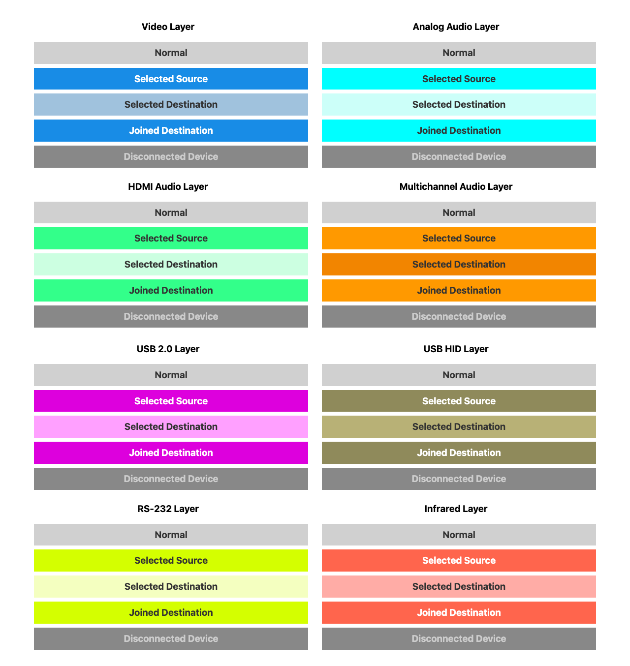
Each routing layer is color-coded. As the user interacts with the Device Rows, the rows will change colors. The normal state is light gray. The disconnected state is dark gray. When a source is selected, it is highlighted its layer color (e.g. blue for Video Layer). When a destination is selected (but prior to clicking the take button), it will be colored a slight variation of the base layer color. After a source has been joined to a destination, then the destination row will be highlighted its layer color just as with the source row.
Device Row Submenus
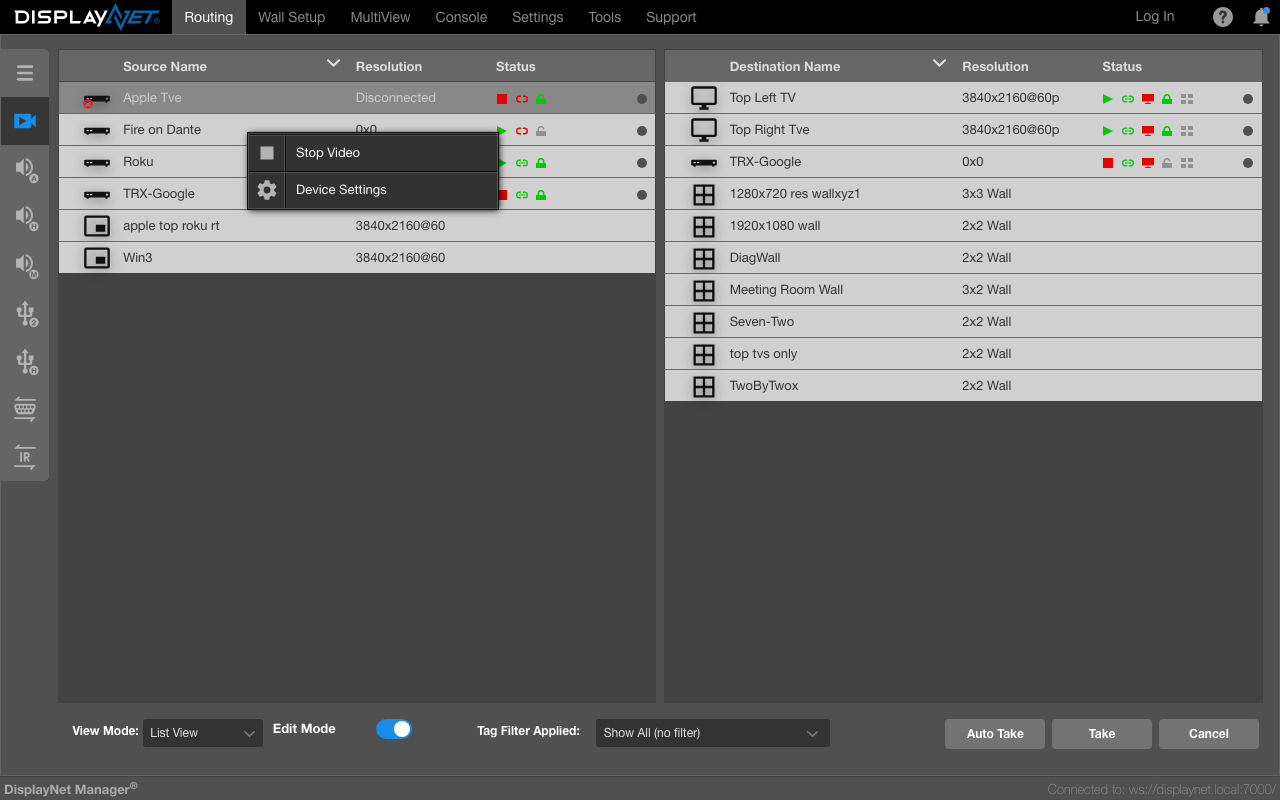
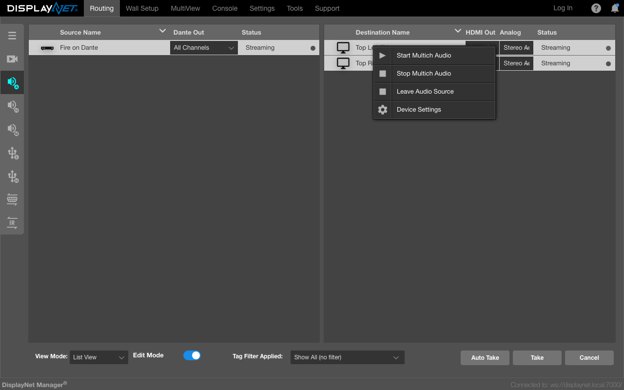
Right-clicking on a Device Row will bring up a menu with a Device Settings option, as well as other options depending on which routing layer is being used and whether the device is connected.
Video Layer submenu example:
Analog Audio Layer submenu example:
Remove Device Submenu example:
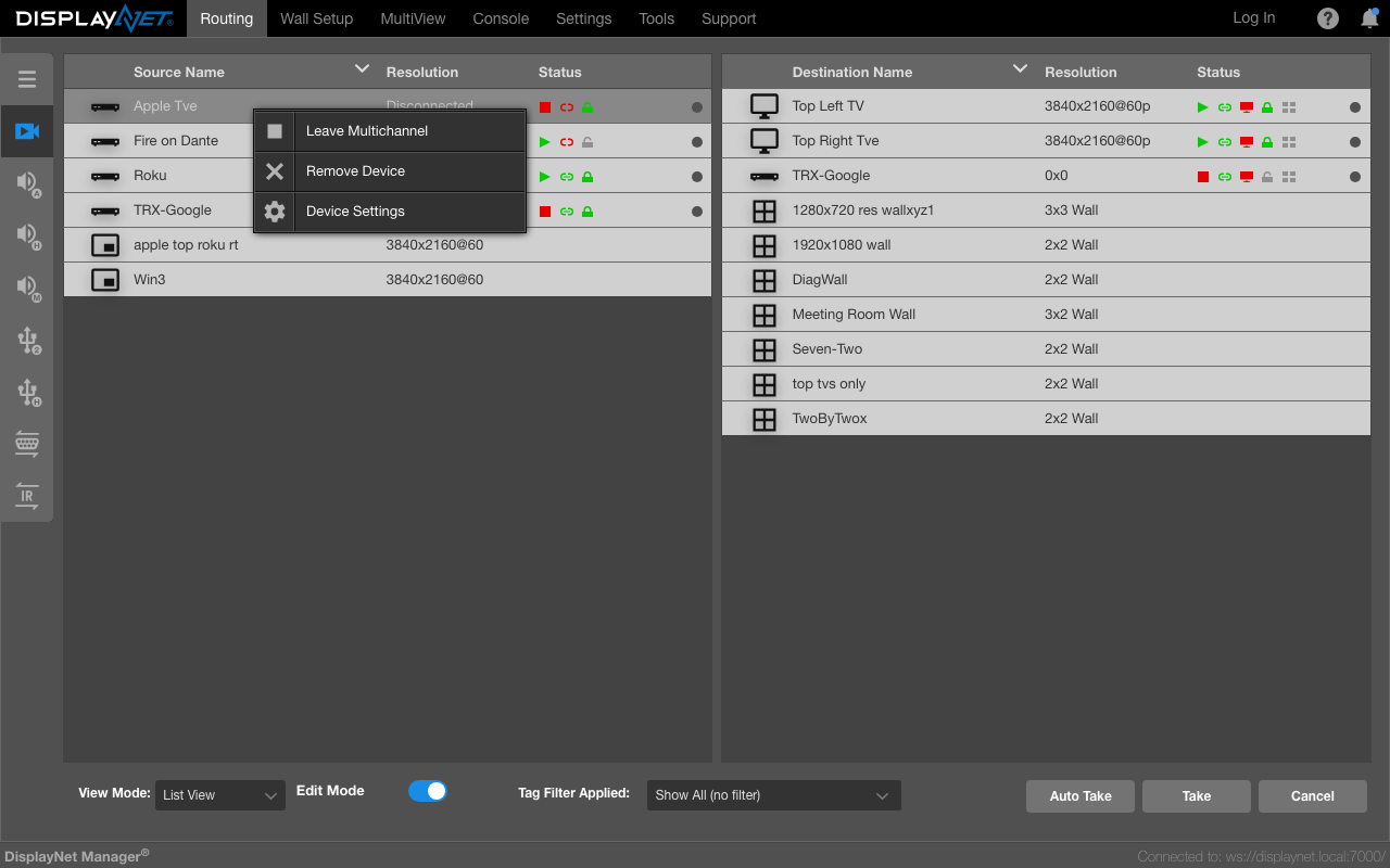
This option removes a disconnected device from the list of devices in the routing tab.
The option to "Remove Device" is only available on a disconnected device.