
System Installation
This guide provides step-by-step instructions for installing a complete DisplayNet system from initial hardware setup through final configuration.
Pre-Installation Overview
This section describes how to setup a dedicated DisplayNet AV network. In this configuration, the DisplayNet AV-over-IP network is set up with minimal or zero interconnections with the rest of the IT network. This is the recommended configuration for DisplayNet systems. For a deeper discussion of other possible configurations, please contact DVIGear technical support.
Step 1: Network Switch Installation
10GbE Network Switch Setup
Prior to installation, ensure that the 10GbE network switch includes the necessary features and is properly configured with the settings required for DisplayNet.
Next, mount the switch into its environment according to the switch manufacturer's instructions. The DisplayNet endpoints and the DisplayNet server will be connected to the switch at a later point in the installation.
Step 2: DisplayNet Server Installation
DisplayNet Server Setup
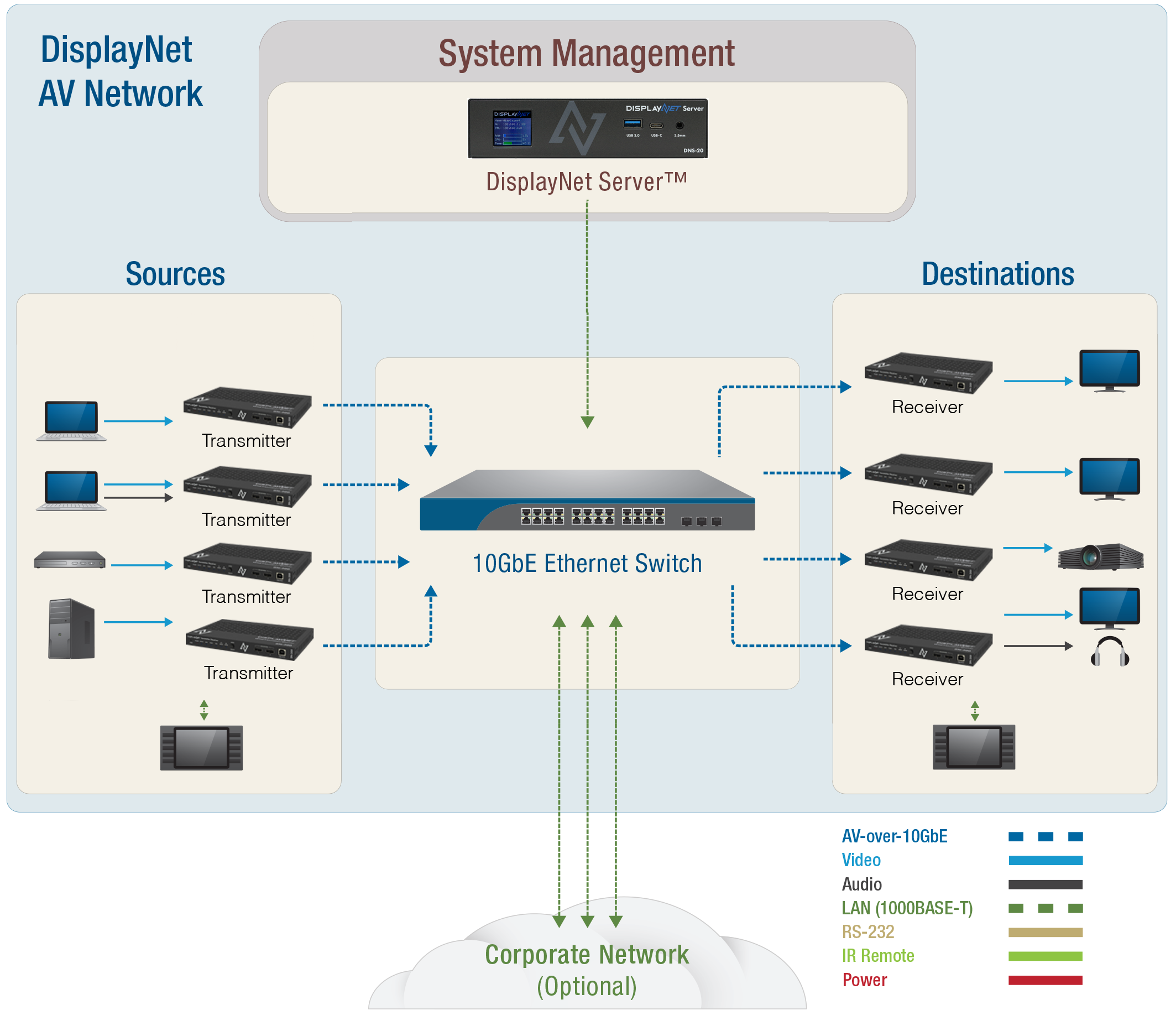
The DisplayNet server serves as the interface between the control equipment/software and the endpoints. It can be accessed either directly, or via the network.
Direct Access Setup
First, connect any peripheral devices such as a keyboard and mouse to DisplayNet server as needed. Connect a monitor supporting up to 1920x1080 resolution to the HDMI output port on the server.
By default, the endpoints and the server have DHCP mode enabled. Consequently, if there is no DHCP server is present, then all devices will obtain their network settings using APIPA. If DHCP or APIPA is used, the endpoints will be reachable from the server and their network settings should not conflict.
The host name of the server is set to "displaynet" by default. The Control Network may be plugged into an external network for control access, while the AV network port should be plugged into the 10GbE AV switch. If the DNS-20 Server is used, the IP addresses assigned to each network interface will appear on the front display.
Do not connect the AV Network to a 1GbE LAN port on a DisplayNet TX or RX. While the server may work in this configuration, all control of the system will be lost if the device that the server is connected to were to lose power or otherwise fail.
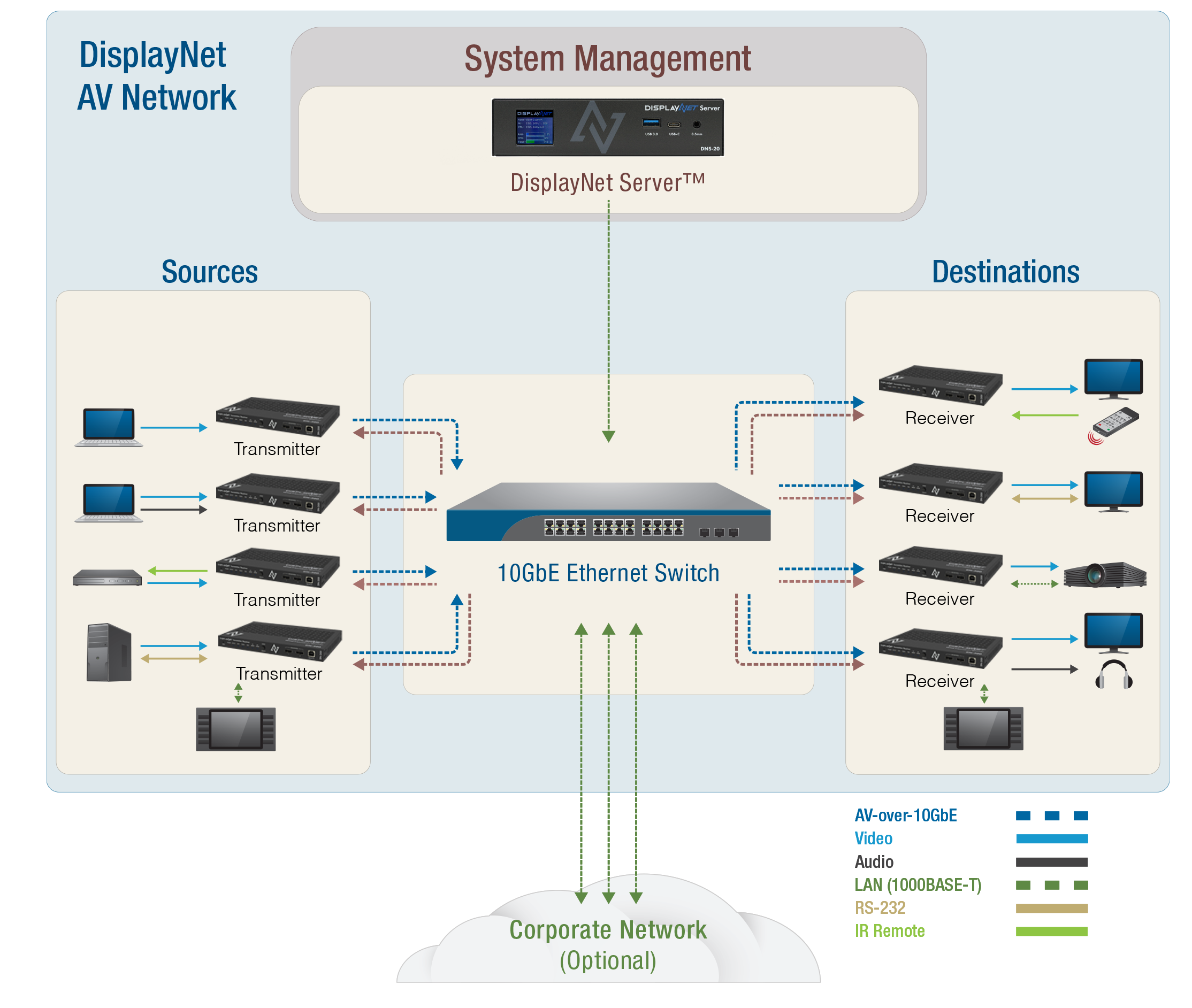
Only a single DisplayNet Server should be actively used in a system at any given time. DisplayNet does not support multiple concurrent operating servers. If multiple server attempt to communicate with endpoints simultaneously, only a single server's commands will be recognized, causing unpredictable behavior.
Only a single DisplayNet Server should be actively used in a system at a given time. Please contact DVIGear technical support for full details.
An Uninterruptible Power Supply (UPS) is highly recommended for the DisplayNet server and should be considered to be an essential part of any system.
Step 3: Hardware Mounting
Mounting DisplayNet Hardware
There are a variety of options available for mounting the DisplayNet devices as well as the other components used in the system. Each DisplayNet transmitter and receiver device comes with a pair of mounting brackets for installation on furniture or other surfaces. Additional rackmount solutions are available from DVIGear, please contact support for further information.
Continue with installation by mounting the DisplayNet devices as needed. For device-specific mounting instructions, refer to your hardware model documentation.
It is typical for DisplayNet devices to operate at high temperatures. Care must be taken to ensure that airflow across each device is not restricted in any way. In rack-mounted applications, the use of fans for forced-air cooling of DisplayNet endpoints is highly recommended.
Step 4: Device Connections
Connecting Video and Audio
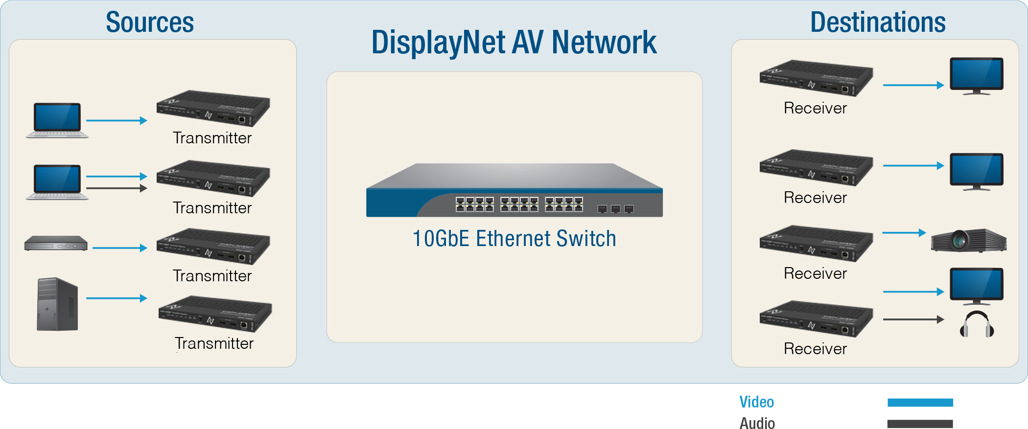
Connect the video sources to the HDMI Inputs on the DisplayNet Transmitters. Connect the video displays to the HDMI Outputs on the DisplayNet Receivers. Connect any analog audio source devices to the 3.5mm Stereo Analog Audio Input Jacks on the TX devices. Connect any analog audio destination devices such as a speakers or headphones to the 3.5mm Stereo Analog Audio Output Jacks on the RX devices. If the audio jack on any TX devices will be configured as an output, connect the audio destination devices to the TX devices as needed.
Optional: Connecting 1GbE LAN
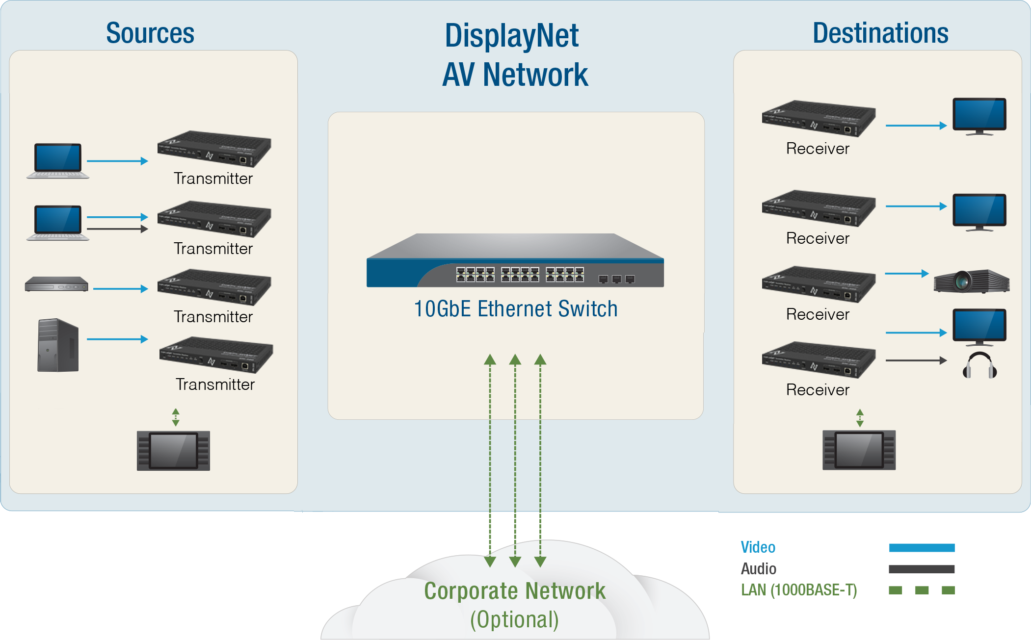
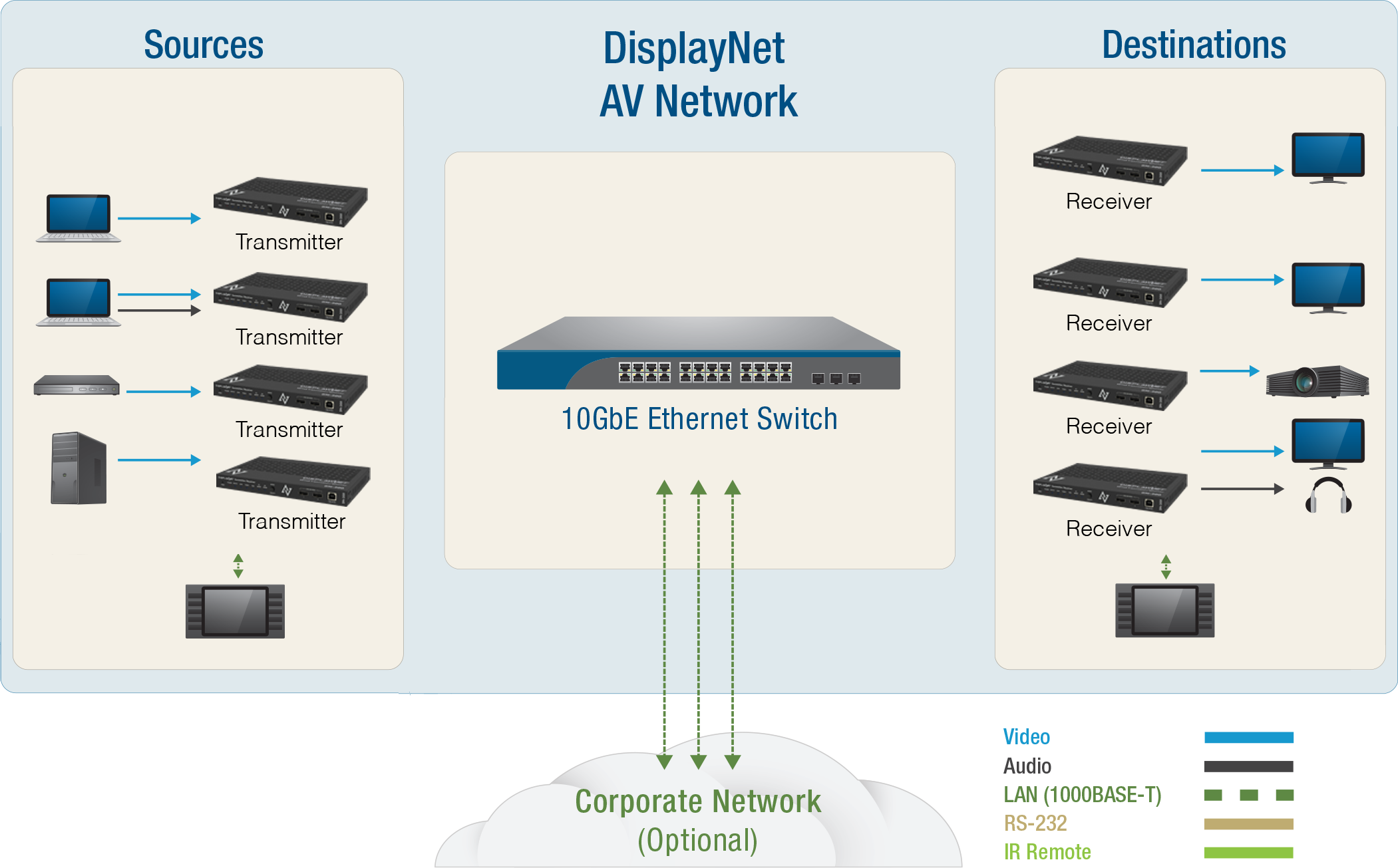
Every DisplayNet device is equipped with a 1GbE LAN port that provides 10/100/1000Mbps network connectivity at each and every endpoint. Connect compatible network enabled devices to the 1GbE LAN port on the transmitters and receivers. Note that any devices connected to the 1GbE LAN port will be routable within the same network used by DisplayNet.
The 10GbE port is designed to connect to compatible DVIGear products and 10GbE network switches only. Do not connect any device to the 10GbE port of this product unless you are sure it is compatible. Please use the preferred cable termination scheme (T568B) for all 10GbE connections throughout the installation.
Use of the 1GbE port may interfere with video traffic at certain resolutions, depending on the amount of total bandwidth used by both the 1GbE device and the routed stream(s).
Connecting RS-232
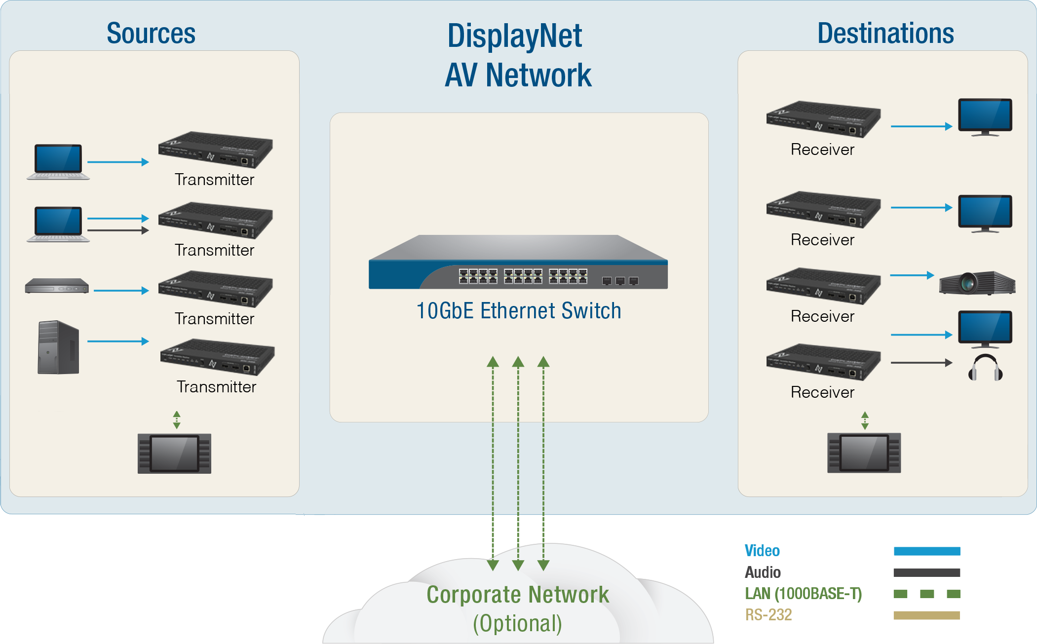
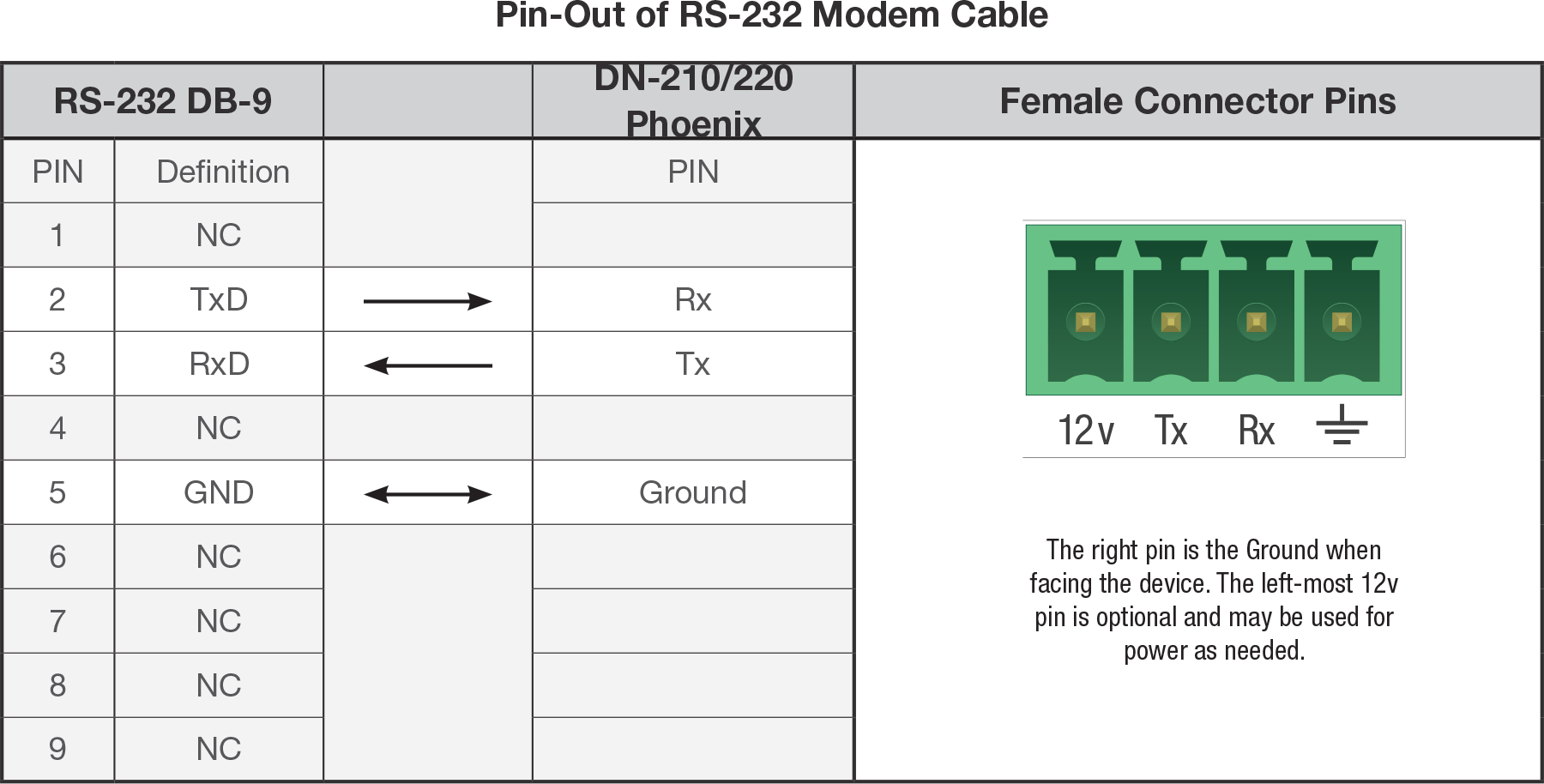
Each device includes 1x male Phoenix connector for RS-232 communication. Use these to wire the serial cables according to the pin-out diagram and table below. Note that inside the DisplayNet devices, the RS-232 connection is straight-through. Depending on how the peripheral devices are set up, the cables should be wired in a crossover or straight-through configuration. Once the cables are assembled, connect the peripheral devices to the devices using the serial cables.
Connecting Infrared (IR)
DisplayNet endpoints support both bidirectional and unidirectional IR communication. An IR transmitter is supplied with each TX and an IR receiver is supplied with each RX. The IR receiver connects to the IR In port and the IR transmitter connects to the IR Out port. The IR receiver will accept IR signals from a device such as a remote control and pass them through over the network to the listening DisplayNet device. The IR transmitter connected to the listener will then transmit these signals to the targeted device being controlled. If necessary, an additional pair of IR TX/RX devices can be purchased and installed for full bidirectional communication. For IR communication, any DisplayNet device may communicate with any other DisplayNet device. For instance, an RX may send commands through another RX. Additionally, command injection mode can be used to send/receive IR communications between the control layer and the endpoints.
Connecting 10GbE to the Switch
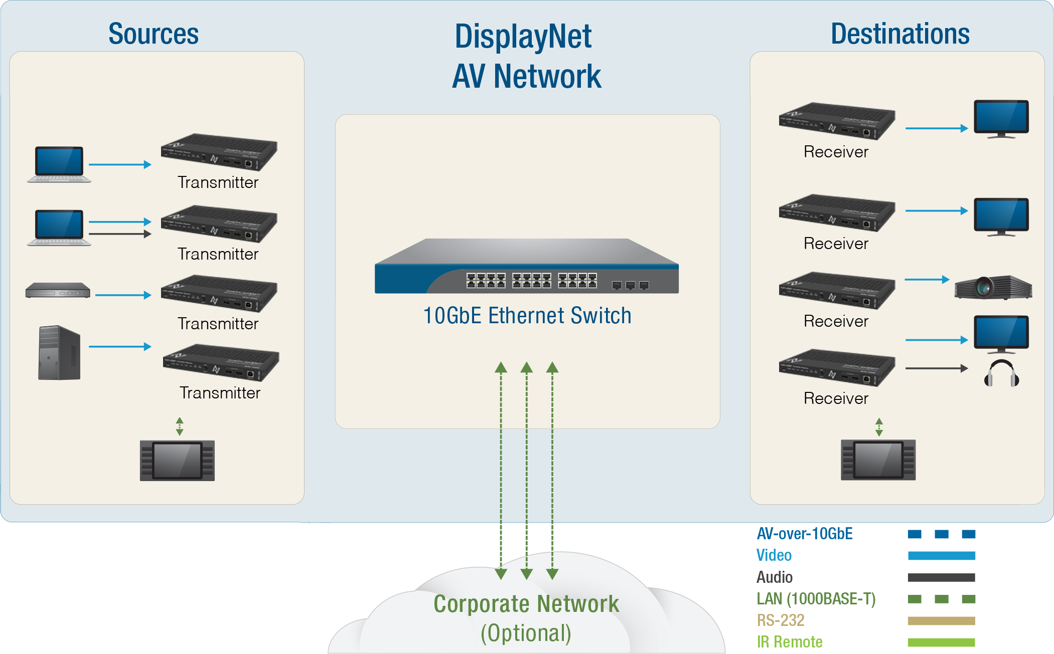
Once all peripheral devices are properly connected to the TX and RX devices, connect each DisplayNet device to the 10GbE network switch using the appropriate cables and termination.
Step 5: System Power On
Power Up Sequence
Once all the equipment is properly mounted and all the connections are in place, the system must be powered on in the correct sequence.
1. Network Switch
The 10GbE network switch should be powered on first. If a UPS battery backup is being used for the switch, then install the UPS according to the manufacturer's recommended procedure. Next, supply power from the UPS to the network switch following the steps recommended by the switch manufacturer. Allow the boot process to complete. Some switches can take up to five minutes to complete their boot process.
2. DisplayNet Server
Next, connect power to the DisplayNet Server. If present, install the UPS backup power first, and then supply power to the server using only the power brick and cord supplied with the server. As mentioned previously, only a single server should be actively used at any given time.
In mission-critical applications, it is recommended to have uninterruptible power supply units connected to both the network switch and the DisplayNet server.
3. Display Devices
Next, power on the display devices and other peripherals connected to the DisplayNet RX devices.
4. DisplayNet Endpoints
Next, connect power to the DisplayNet transmitters and receivers. To do this, plug the included external AC power adapters into the devices, twist the plug 90˚ clockwise to lock the plug in place, and then plug the adapter into a power outlet. Only use the AC power adapters supplied with the DisplayNet devices or a compatible power distribution unit.
For specific power requirements and PoE+ options, refer to your hardware model documentation.
An optional Power Distribution Unit (DVIGear p.n. DVI-7520-PDU) is available to supply power to DisplayNet endpoints within a rack environment. The DVI-7520-PDU provides +12VDC power for up to eight (8) endpoints.
5. Source Devices
Finally, power on the source devices and other peripherals connected to the DisplayNet transmitters.
Be certain to only use the power cables and adapters supplied by the manufacturer of each device.
Step 6: Initial Configuration
Server Access and Setup Wizard
Once the system is powered up and network connections are established:
-
Access DisplayNet Manager by opening a web browser and navigating to
http://displaynetorhttp://displaynet.localDNS-20 DisplayNet ServerThe DNS-20 DisplayNet Server shows the IP addresses and hostname on the front panel screen that can be used to access DisplayNet Manager.
-
The system will automatically redirect you to the Setup Wizard for initial configuration
-
Complete the Setup Wizard to configure admin accounts, network settings, and security options
-
After completing the Setup Wizard, the system will be ready for device discovery and configuration
Device Discovery
After completing the Setup Wizard:
- DisplayNet Manager will automatically detect DisplayNet devices on the network
- Devices will appear in the Sources and Destinations panels
- You can begin configuring routing, device settings, and system organization
For hardware-specific setup procedures (such as mode switching, special mounting configurations, or unique power requirements), refer to your specific hardware model documentation in the DisplayNet Hardware section.