Signal Routing
DisplayNet enables sophisticated signal routing through standard IP networking protocols, supporting multiple independent data streams over a single 10GbE connection.
Multi-Layer Signal Distribution
DisplayNet is able to accept multiple data streams (Video, Audio, IR, RS-232, and 1GbE). Each individual stream is packetized and sent out over a shared 10GbE connection. By packetizing streams, each data stream may be routed separately to one or many destinations through standard Layer 2 / Layer 3 Ethernet network addressing protocols. Data channels can also be routed independently of each other.
The HDMI signal from one source may be routed to a certain destination, while the analog audio input from that source may be routed to a different destination.
DisplayNet makes use of several network addressing methods. As with any networked device, each DisplayNet transmitter and receiver ships with a unique hardcoded MAC Address, which is used by the DisplayNet API Engine to maintain identities and groups of transmitters and receivers on a DisplayNet network. Each device also receives an IPv4 address, which is used to route data between devices. DisplayNet endpoints do not support IPv6.
DisplayNet systems make use of IP unicast, multicast, and broadcast to route data for video, audio, RS-232, and IR. Additionally, DisplayNet makes use of the "zero" network broadcast address 255.255.255.255 for functions such as device discovery (using "hello" packets) as well as allocation of multicast addresses (using "advertising" packets). This 255.255.255.255 broadcast address is also used when sending RS-232 or IR data to all devices.
IP Addressing
The role of the IP Address is to define the exact device and its location on a network in order to route data between network devices. IP addresses may be assigned dynamically, automatically, or manually. By default, DisplayNet devices are set to Dynamic Host Configuration Protocol (DHCP) mode. In this mode, if a DHCP server is present on the network, then all the DisplayNet transmitters and receivers will automatically be assigned IP addresses by the DHCP server. DHCP mode prevents duplicate IP addresses from being assigned and can simplify network management.
When the devices are set to DHCP mode and there is no DHCP server found on the network, then each DisplayNet device will automatically assign itself an IP address using Automatic Private IP Addressing (APIPA) scheme in the 169.254.X.X range with a subnet mask of 255.255.0.0. The devices will use Address Resolution Protocol (ARP) to ensure that there are no IP address conflicts. The APIPA scheme is widely adopted in many platforms such as Windows and Linux.
A static IP address is one that is assigned manually and permanently remains with the device until a manual change is made. This can be done using DisplayNet Manager or with the DisplayNet API commands.
In any case, changes made to the IP settings of a device are stored in non-volatile memory and kept until they are changed, or the device is reset to factory default values.
For ease of management, DVIGear recommends the use of a DHCP server to manually assign reserved IP addresses to individual devices using the MAC address of each device. This allows for centralized configuration of all of the devices on the network, and also allows each device to retain its IP address assignment in the event of a factory reset.
It is important to ensure that the DisplayNet server and any control devices on the network are configured properly so that they may communicate with the DisplayNet devices. The DisplayNet server runs Linux and is set to automatically obtain its network settings. If a DHCP server is present, then the DisplayNet Server will obtain its IP address from the DHCP server. If no DHCP server is present, then the DisplayNet Server will use APIPA to assign itself an IP address. This ensures that the DisplayNet Server receives a non-conflicting IP address in the same subnet as the transmitters and receivers.
It is strongly recommended to take care when configuring the network settings of DisplayNet devices. Each IP address must be both unique and routable. Otherwise, the device may be rendered unreachable over the network. In this event, it is necessary to reset the device to factory default settings using the front panel button.
When using manual IP mode, it can be helpful to have a DHCP server available for the initial system setup. By default, the DHCP server will automatically assign IP addresses to each device without any conflicting addresses. From there, the devices can be configured to use static IP addresses as planned.
Video and Audio Distribution
DisplayNet provides matrix switching functionality through the use of IP multicast. Multicasting is the process of routing network traffic to select groups of devices using the Internet Group Management Protocol (IGMP). One or more devices can register membership to a group and receive data from the device sending to the address assigned to that group. The network switch creates on-the-fly routing tables to ensure that only devices subscribed to a certain multicast address receive data from that sending device. IP v4 multicast addresses are restricted to a select range from 224.0.0.1 to 239.255.255.255.
DisplayNet primarily uses IP v4 multicast in order to route Video or Audio data from a single transmitter to one or more receivers. However, in some cases, Multicast addressing is also used to send RS-232 or IR data. When a source is connected to a DisplayNet transmitter, the TX is assigned an unused multicast address in one of the available ranges shown below. DisplayNet only uses multicast addresses in these ranges:
| Type of Signal | Range |
|---|---|
| Available for Video and Audio | 224.1.1.1 to 224.1.1.252 |
| Reserved for sending RS-232 and IR data to all TX | 224.1.1.253 |
| Reserved for sending RS-232 and IR data to all RX | 224.1..254 |
| Available for Video and Audio | 224.1.1.255 |
| Available for Video and Audio | 224.1.2.0 to 224.1.2.255 |
| Available for Video and Audio | 224.1.3.0 to 224.1.3.255 |
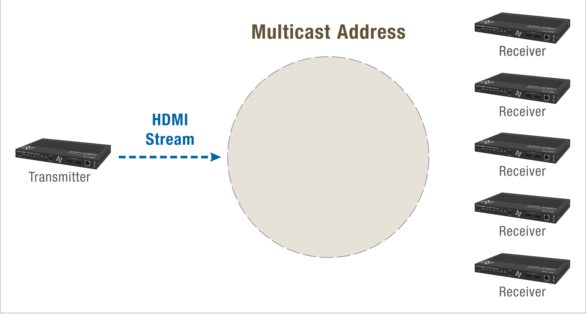
Once an address is reserved by a transmitting device, it begins sending video data to that address. One or more receivers may subscribe to this multicast address and receive IP packets from the transmitter via the network switch. IGMP snooping allows the switch to monitor and map the traffic to ensure that only subscribed devices receive data from the transmitting devices. Without IGMP snooping, multicast packets are broadcast to all ports, which causes network flooding and oversubscription. For DisplayNet systems to function properly, IGMP snooping must be available and enabled.
One or more receivers may register to a multicast address group to subscribe to the stream from a transmitter. The data packets sent from the transmitter to the multicast address will then be routed by the switch to the ports connected to the receivers. The source video will be displayed on the monitors connected to the receivers. Receivers may leave or join this multicast group as needed.
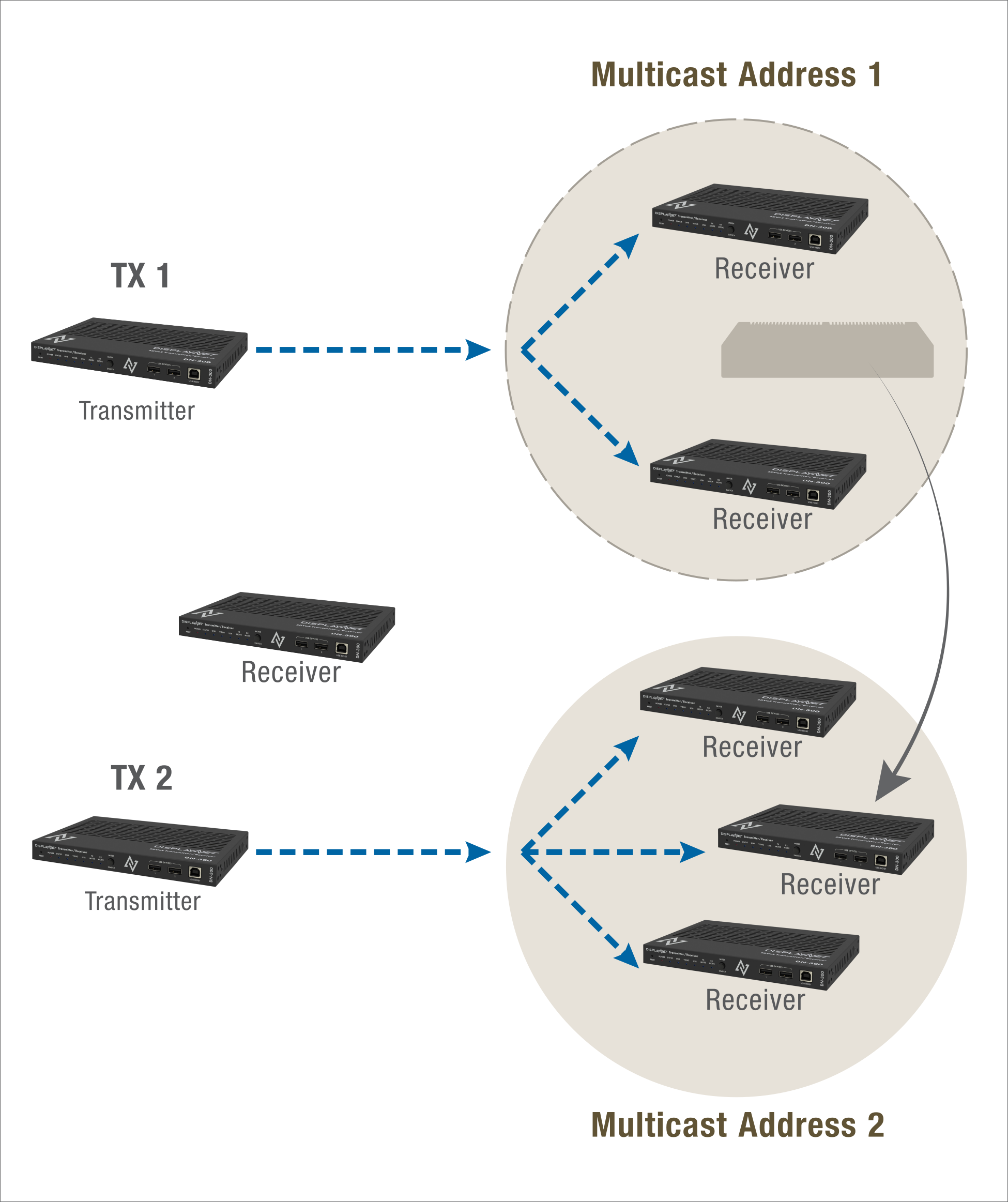
Additionally, the Fast Leave option available in many 10GbE network switches enables receivers to quickly unsubscribe from one multicast group and join another group very quickly. Fast Leave allows for seamless switching for resolutions of up to 4K (UHD). Without the Fast Leave option, seamless switching is only available for resolutions of up to 1920x1080 /60p. Multicast addressing is also used for audio routing.
Control Signal Routing
RS-232 and IR Communication
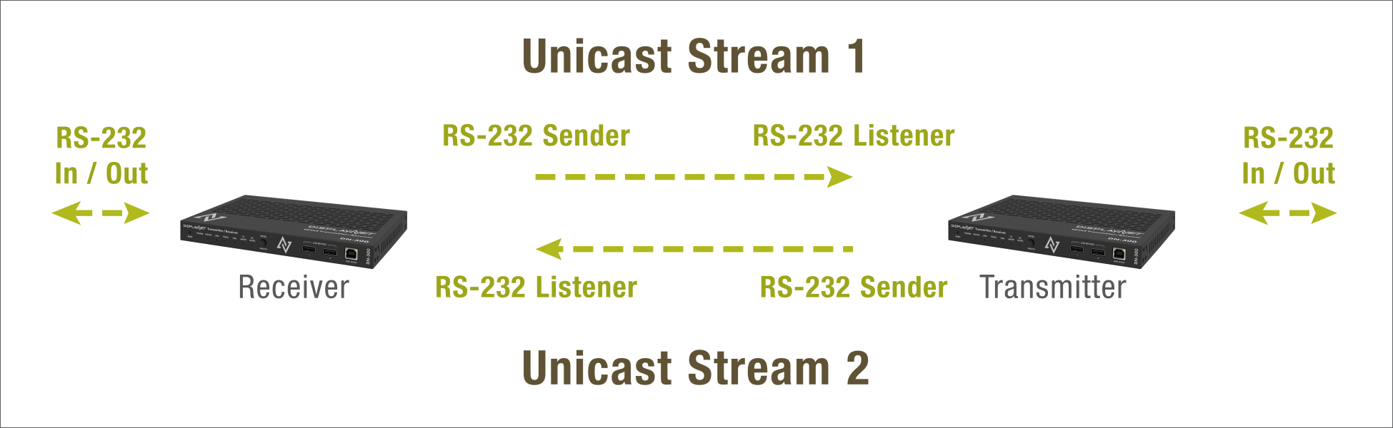
For most RS-232 and IR communication, DisplayNet makes use of IP unicast addressing. Unicasting is done when data is only sent to a single specific destination IP. In contrast to video and audio data, RS-232 or IR data may be sent from any DisplayNet endpoint (TX or RX) to any other DisplayNet endpoint (TX or RX). For example, a DisplayNet RX may send RS-232 data to a DisplayNet TX. Or two receivers may communicate with each other. In any case, when two DisplayNet devices are joined together for RS-232 or IR communication, one is defined as a sender and the other as a listener. The result is a unidirectional data tunnel where all RS-232 or IR data coming into the sender's RS-232 or IR In port is transmitted over the network to the listener device using unicast IP protocol, and the data is sent out on the receiver's RS-232 port or IR Out port.
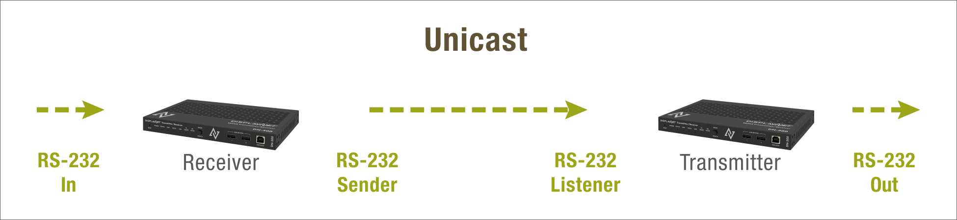
To establish bidirectional communication between the two devices, each device must be joined twice; once as a sender and again as a listener.
A device can also send RS-232 or IR data to all transmitters or all receivers using pre-defined multicast addresses: 224.1.1.253 (send to all TX) or 224.1.1.254 (send to all RX). However, RS-232 and IR data cannot be sent simultaneously to a range of many devices (multi-unicast).
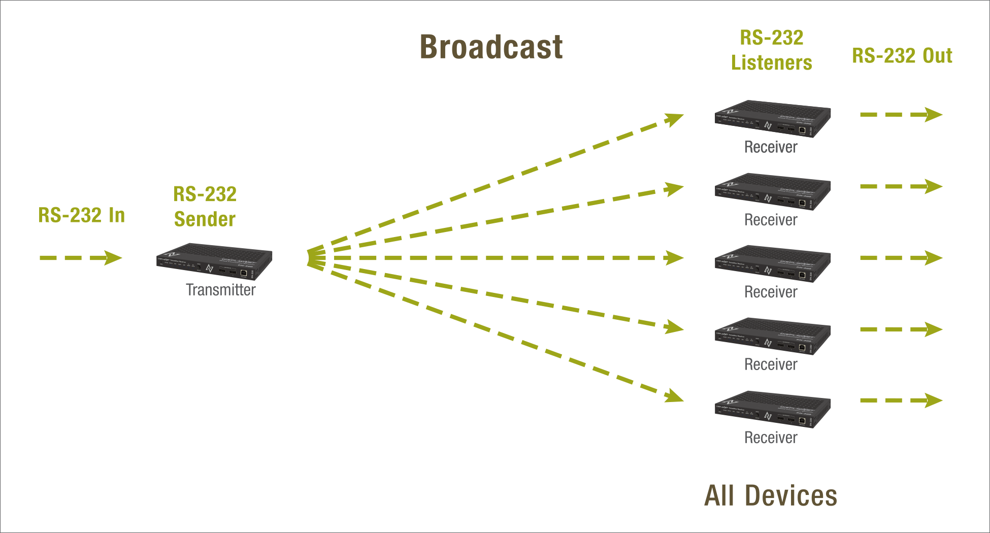
Finally, the broadcast address 255.255.255.255 is used to send RS-232 or IR data to all devices. There is nothing that prevents multiple sender devices from being joined to a listener device. However, since RS-232 or IR data is sent one character at a time, data sent from multiple senders will arrive at the listener in an arbitrary sequence (order). In this case, the device connected to the RS-232 port will need to rely on higher level session or application protocol to separate incoming characters and reconstruct the data from individual devices.